Level: Basic
Required Knowledge: None
Keywords: Process Simulation, EOS Calculations, Optimization
Pipe-It Utilities: Streamz Separator, Strexzel, Pipe-It Optimizer, Streamz Library, Streamz Tabulator, Streamz Copier, Linkz, Composite.
The objective of this tutorial is to optimize the process conditions of a simple 4-stage separation train using Pipe-It.
Conditions (pressure and temperature) of the three first stages are variables of the optimization problem. The objective is to maximize the final oil volume. Constraints on vessel temperature and pressure are also considered. The full optimization problem is described later. Note that the feed stream to the process is constant.
You can download the required input files here. You will need to login to the server using your existing uszername and password or register as new user.
Download the file : "Multi-Stage_Process_Optimization.zip" and un-zip it on your disk.
The folder "Multi-Stage_Process_Optimization" contains several files and one sub-folder:
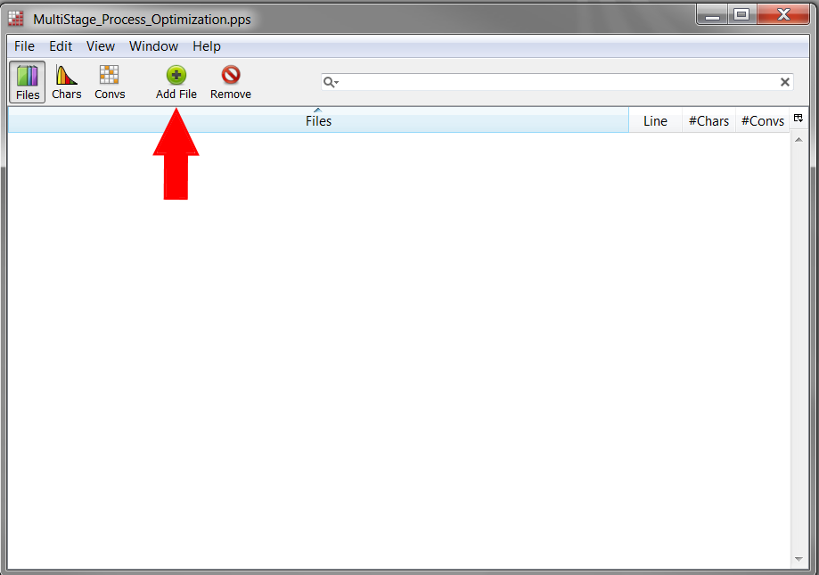
The Fluid Characterization Library (also called Streamz library) contains all fluid descriptions (e.g EOS models) and conversions (EOS volume calculation) needed in the Pipe-It project. Each new fluid description needs to be added to the Streamz library following this set of instructions:
![]()
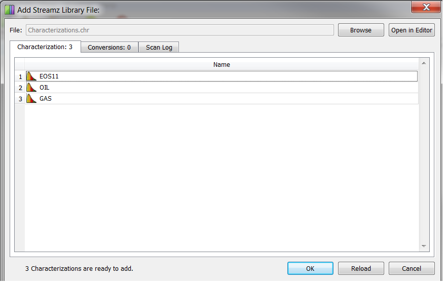
Three new characterization have been added:
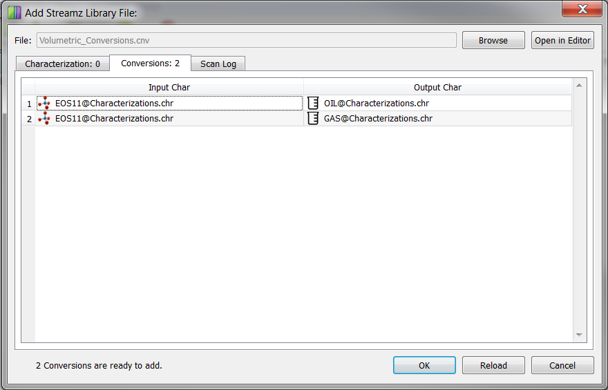
In addition, two EOS volume conversions have been added:
Insert a new resource element on the canvas either by:
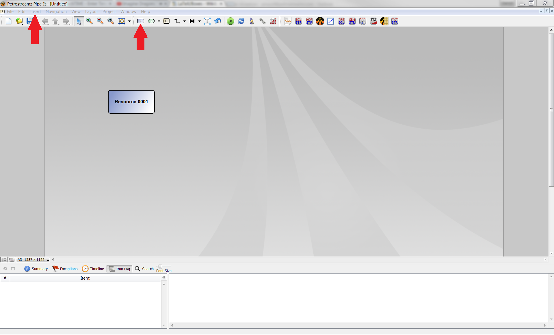
A resource element is always a reference to a file on a hard disk. We first need to link this resource element to a file on the disk. This can be done by right-clicking on the resource element. This operation can also be done by selecting the resource and pressing the touch F of the keyboard.

Select the file "Feed\_2\_process.str" and click on "Save".
This file can be open within Pipe-It by double clicking on the resource element. A new window appears:
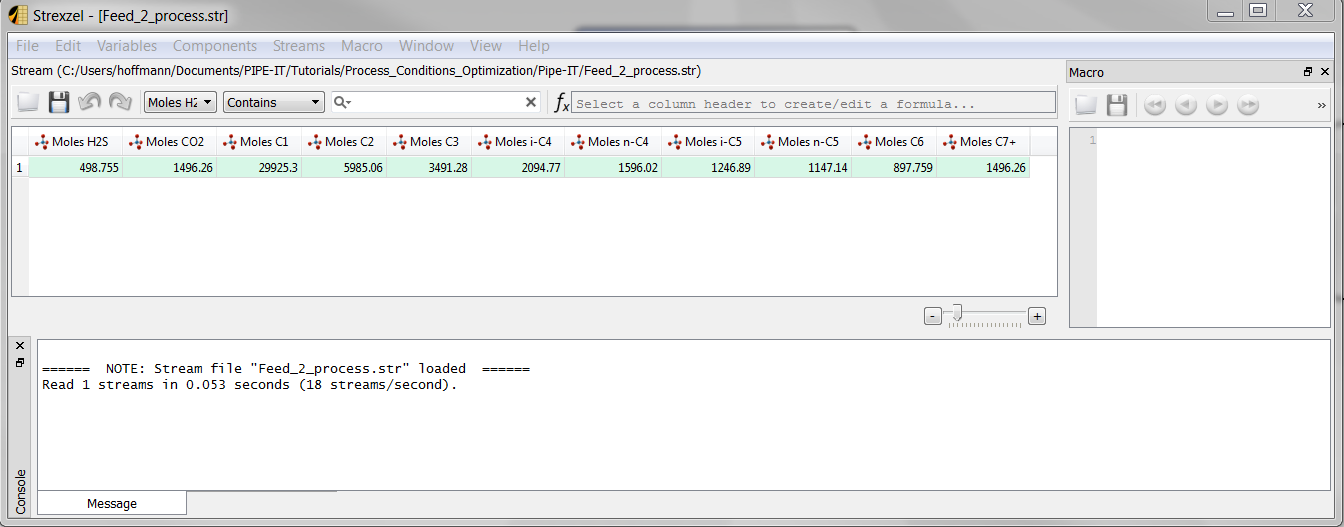
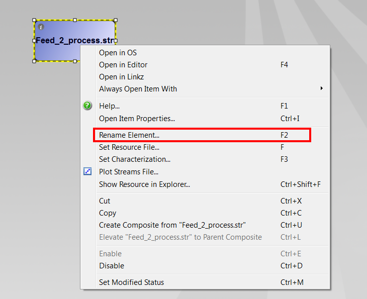
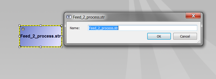
The name of the resource element can be changed by right-clicking on it. This operation can also be done by selecting the resource file and pressing F2.
In Pipe-It, a Stream file (.str) needs to be linked to a fluid characterization in most of the cases. This can be done by right-clicking on the resource element. This operation can also be done by selecting the resource element and pressing F3.
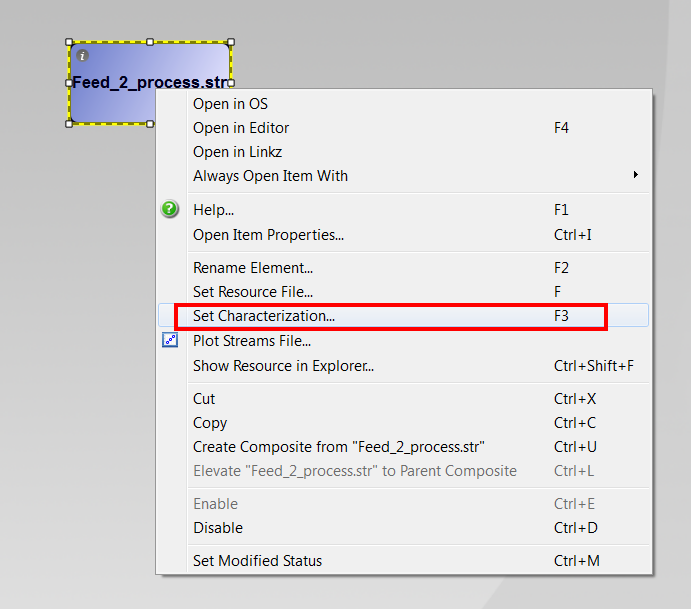
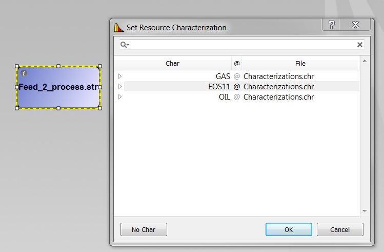
A new window appears. Select the "EOS11" characterization and click on "OK".
In this tutorial, we are going to use Strexzel to insert the process conditions.
First we need to insert a Strexzel process element on the canvas either by:
![]()
Insert a new resource file on the canvas by following the procedure described above. When setting the file, choose the file "Insert_Process_Conditions.stm". Note that this resource does not need to be associated with a characterization. Only Stream files need a characterization.
Insert a new resource element. When setting the file, type "Feed_2_process_w_cond.str" and click on "Save".
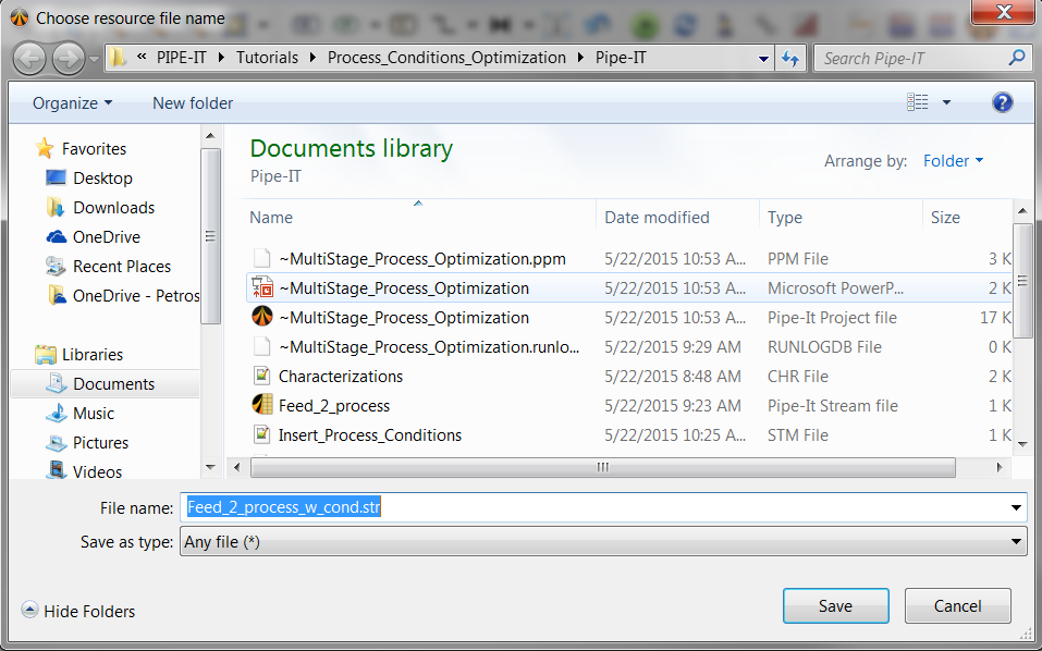
Note that this file does not exist yet, but will be created by Pipe-It. This resource element is linked to a Stream file and needs to be linked to a characterization. Set the characterization "EOS11" to this file, following the procedure described above.
At this moment, the canvas should look like this:
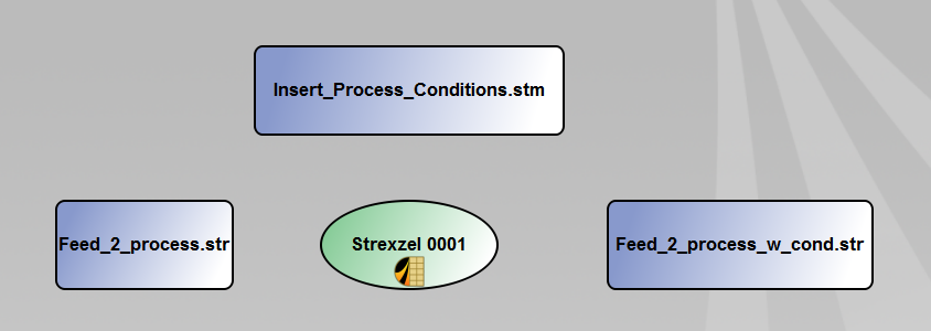
Insert a connector by clicking on the connector icon in the tool bar or by clicking on Insert > Connector. The difference between "Elbow" and "Straight" is only graphical and will not affect the Pipe-It model.

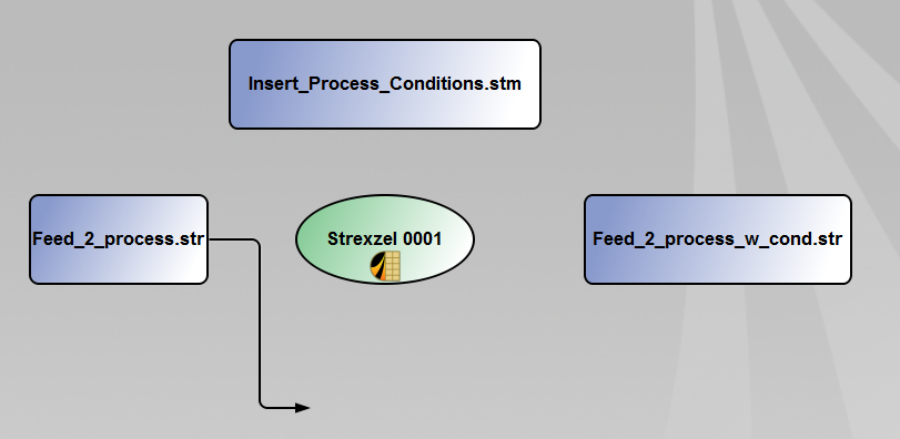
Connect the resource element "Feed_2_process.str" to the Strexzel element. The connector should start from the resource element and be pointing the process element. When the connection is done, Pipe-It gives you several option. You need to indicate if the input resource file is:
In this case, the input resource file is a Stream file.
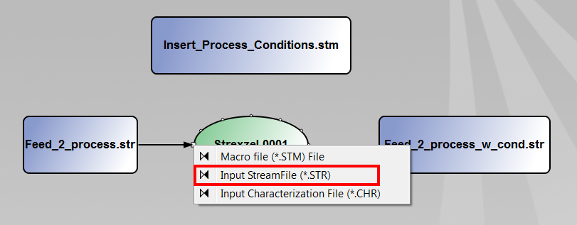
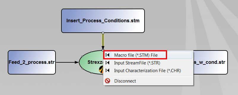
Do the same operation for the resource element "Insert_Process_Conditions.stm". In this case, choose the option "Macro file (.stm)".
The last resource file is an output of the Strexzel process element. The connector should go from the process element and be pointing the resource file. Several options are available. Choose "Output Stream file (.str)".
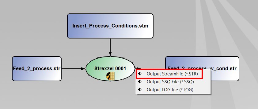
At this moment, your Pipe-It project should look be similar to the following picture. You can run it by clicking on the run button in the tool bar or by pressing CTRL + R on the keyboard. #Run Pipe It?

Note that the output file "Feed_2_process_w_cond.str" has been created while Pipe-It was running. Now, it can be open by double-clicking on it. A Strexzel window appears:

Insert a new Streamz separator element either by:
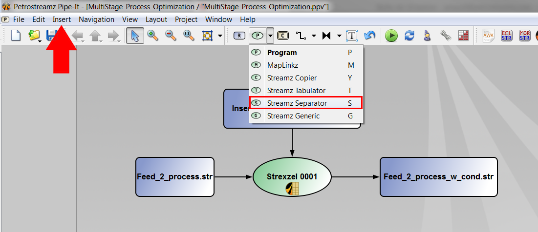
Rename the Streamz separator by right-clicking on it (or pressing F2) and call it "Stage 1".
We now need to insert two resources elements which will be the output of the Streamz separator element:
When setting the files, typewrite "Stg1_oil.str" for the first file and "Stg1_gas.str" for the second file. Both files need to be linked to the same characterization "EOS11".
At this moment, the canvas should look like this:

Use the connector element to make connections between resource files and the separator. The procedure is described here.
When connecting the input file "Feed_2_process_w_cond.str" to the Streamz separator, several options are available. Choose "INPUT STREAMS".
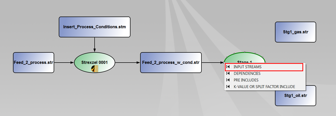
When connecting the Streamz separator to the output files, several options are available. Choose "OUTPUT OIL STREAMS" for the resource "Stg1_oil.str".

Choose "OUTPUT GAS STREAMS" for "Stg1\_gas.str".
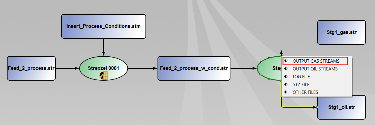
At this moment, the canvas should look like this:

For the moment, we have indicated:
Now, we need to configure the type of separation process we want to model. To do this, double click on the Streamz separator element. A new window appears. Select the "EOS Flash" option to perform an EOS-based flash calculation.
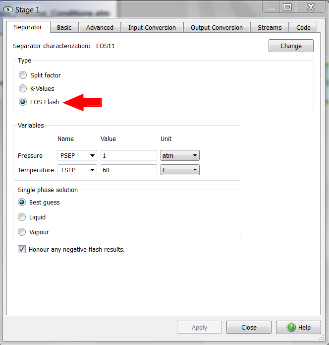
In the section "Variables", you have to define the pressure and temperature for the flash calculation. Use the pressure and temperature we previously defined using Strexzel and a macro file:
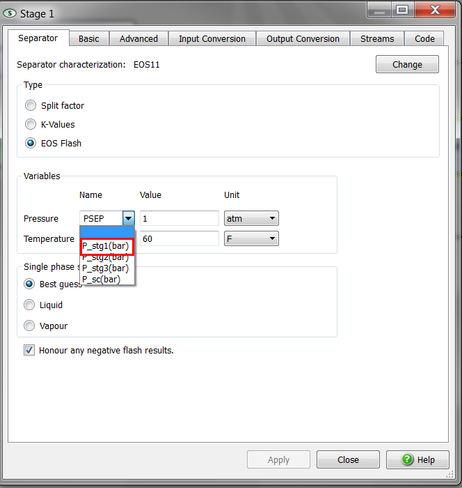
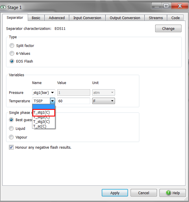
Run the project, following the instructions given here. Pipe-It will perform automatically the flash calculation of the feed stream at the given pressure and temperature, using the EOS model "EOS11". The output files "Stg1_oil.str" and Stg1_gas.str" will be created during the run. You can open them by double clicking on the resource files. They contain respectively the molar rates of all components in the separator oil and separator gas.
Following the previous instructions, insert three additional Streamz separators with the following configuration:
| Separator Name | Feed file | Output file (separator oil) | Output file (separator gas) | Pressure | Temperature |
|---|---|---|---|---|---|
| Stage 2 | Stg1_oil.str | Stg2_oil.str | Stg2_gas.str | P_Stg2 | T_Stg2 |
| Stage 3 | Stg2_oil.str | Stg3_oil.str | Stg3_gas.str | P_Stg3 | T_Stg3 |
| Stage 4 | Stg3_oil.str | Stg4_oil.str | Stg4_gas.str | P_sc | T_sc |
Note that all files need to be set up with the same characterization "EOS11".
After having configured a new separator, it is useful to re-run the Pipe-It project, so the new output files will be created on the disk.
At this moment, the canvas should look like this:
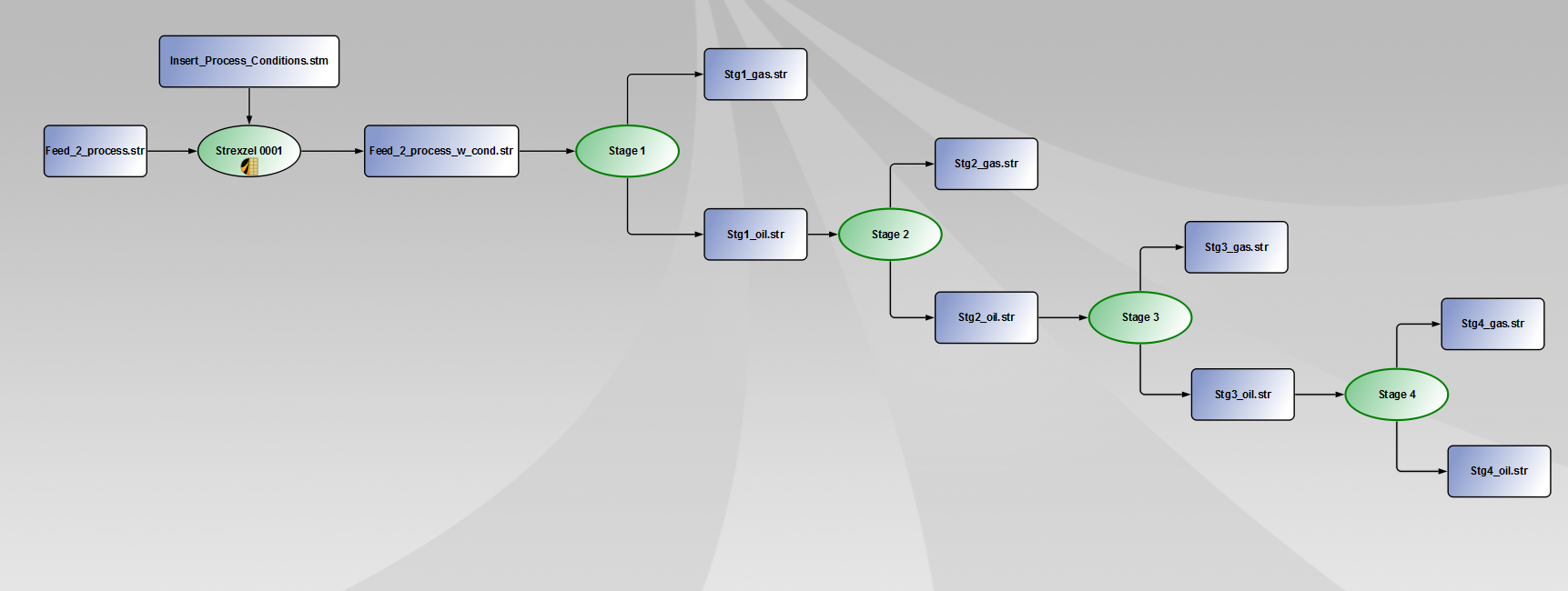
The gas released at each stage of the separation trains need to be commingled into a single stream. This can be done using the "Tabluator" process element of Pipe-It.
First, you need to insert a new tabulator process element on the canvas either by:
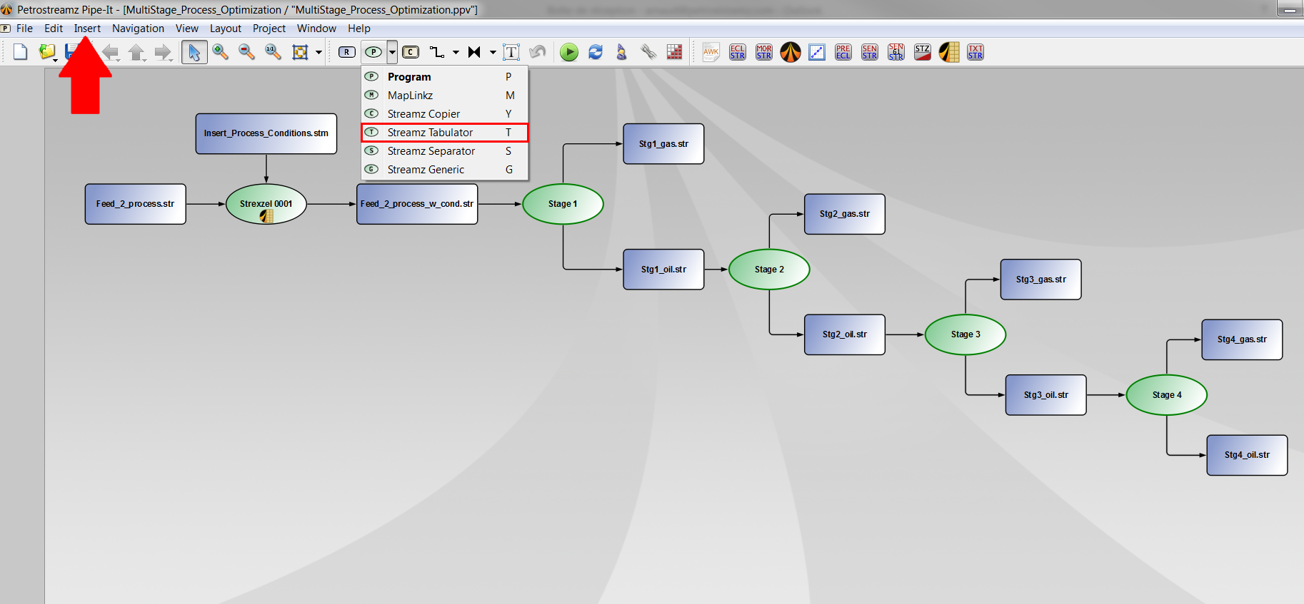
The Tabulator process element will behave like a "mixer". It will gather the input streams and tabulated them in a single output file. Thus, a new output resource element has to be inserted.
Following the instructions given here, insert a new resource element on the canvas.
Typewrite "total_gas.str" for the file name and set the characterization to "EOS11".
Now, we need to connect the different resources elements to the tabulator element.
First, connect the resource element "Stg1_gas.str" to the Streamz Tabulator using a connector. Several connection options are available. Choose "INPUT STREAMS".

Follow the same instructions for the other input streams:
For the output file, set a connect from the tabulator element to the resource element "total_gas.str". Choose the option "OUTPUT STREAMS".

At this moment, the canvas should look like this:

The Streamz Tabulator needs to be configured.
First double-click on the tabulator element. A new window appears.
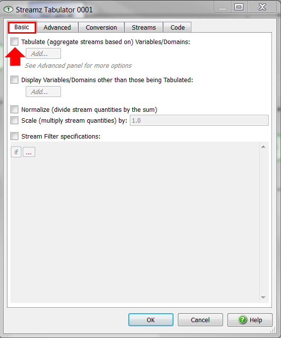
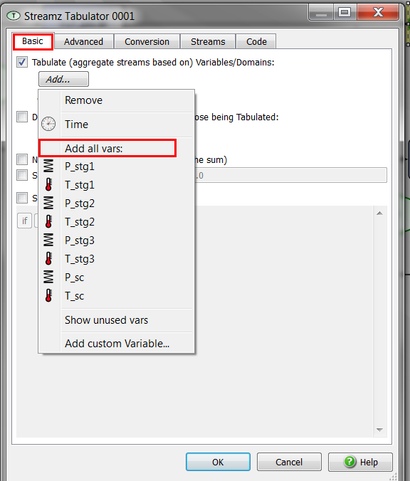
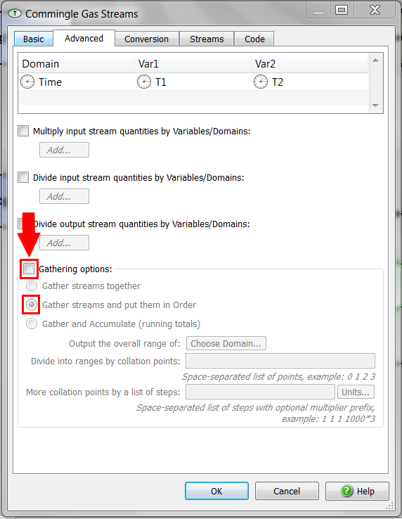
We want to convert the molar rates of the final oil product into a liquid volume.
Insert a new Streamz Copier either by:
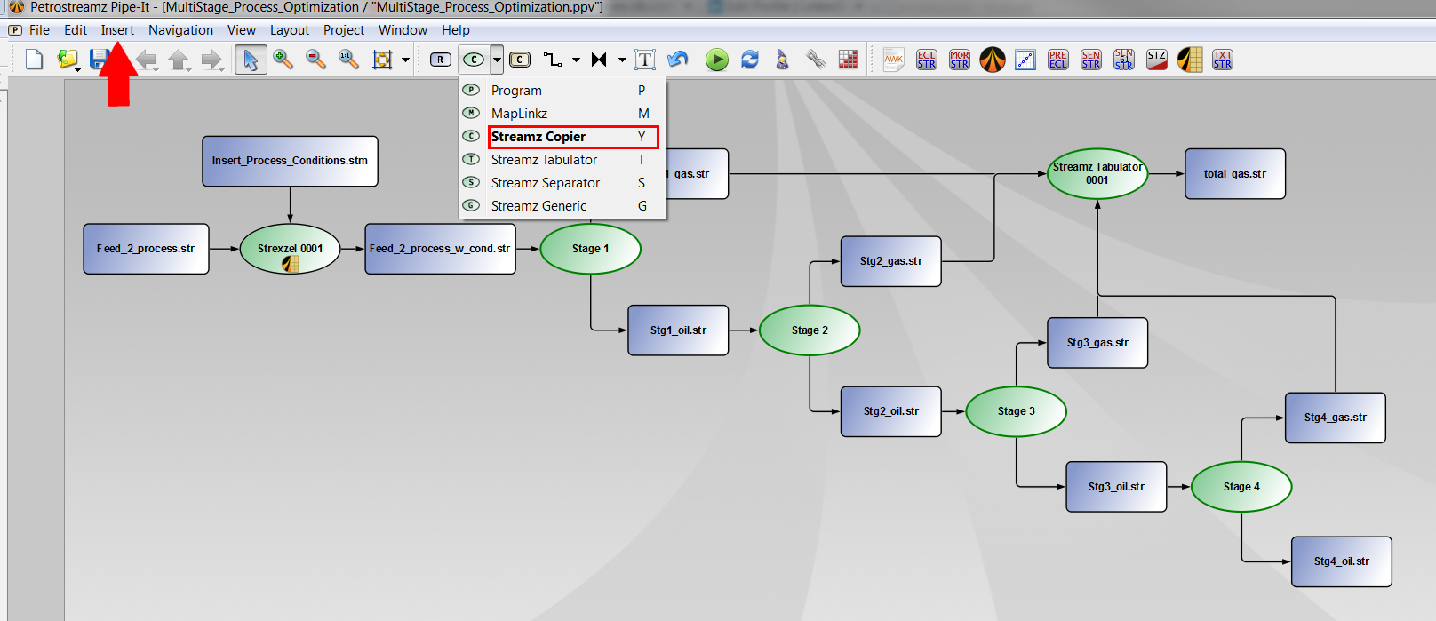
Insert a new resource element following the instructions given here.
Typewrite "Oil_volume.str" as file name and set the characterization to "OIL".
First connect the resource element "Stg4_oil.str" to the Copier element with a connector. Select "INPUT STREAMS".
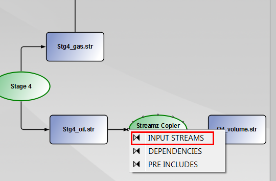
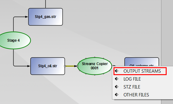
Then, connect the Copier element to the output resource file "Oil_volume.str". Select "OUTPUT STREAMS".
The Streamz Copier element automatically picks up the correct conversion in the Streamz library. You can check this by double-clicking on the Copier element and going in the tab "Conversions".
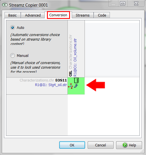
Here, we can see that Pipe-It will perform an EOS calculation to translate moles into volume, using the EOS model. You can check the input file used for the conversion by double clicking on the green square. A new window appears showing the file where the conversion is read from. You can also double click on the file name to open the file.
In our case, we are converting molar rates (described with "EOS11" characterization) into an oil volume (characterized by "OIL"). Pipe-It will automatically use the EOS model to do this conversion.
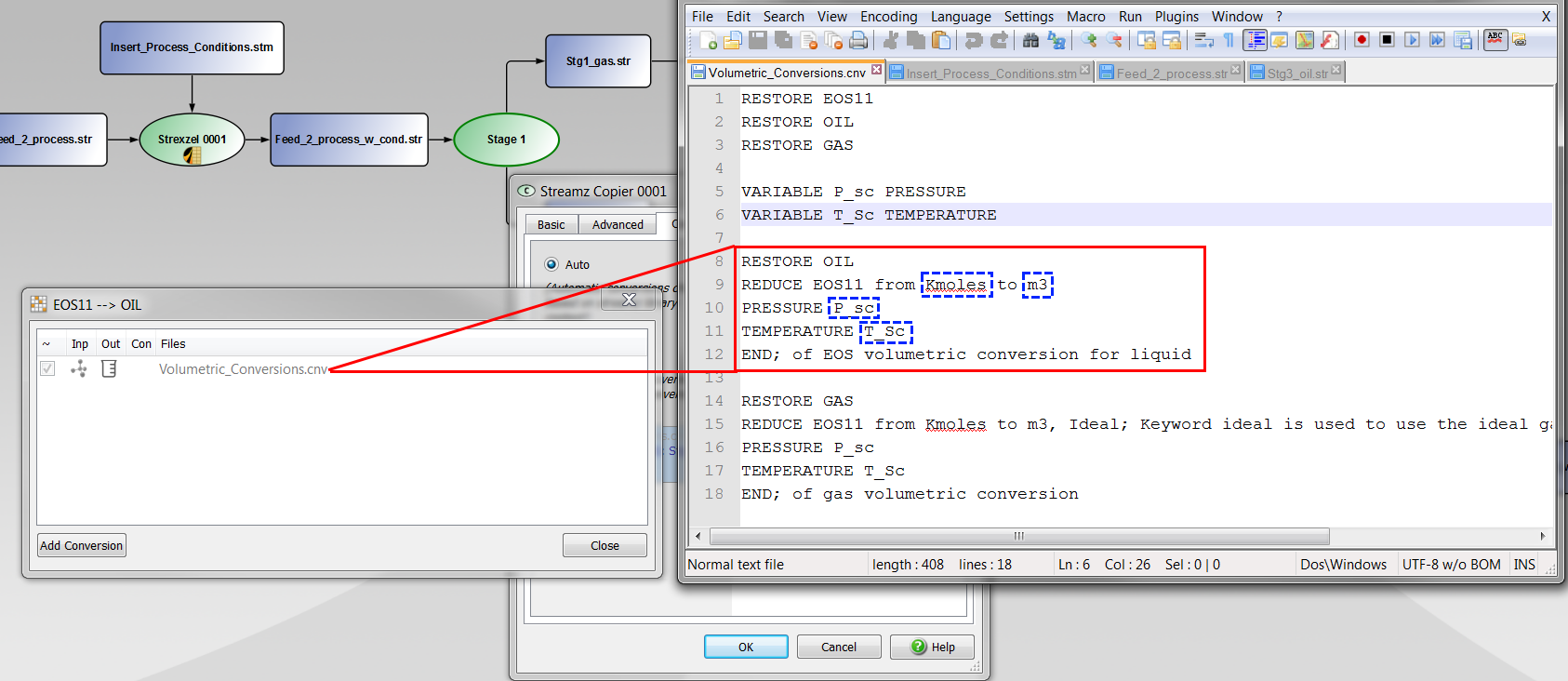
It is important to emphasize here that the volumetric calculation is sensitive to:
Follow the same set of instructions to translate the gas molar rates from the resource file "total_gas.str" to a new resource called "Gas_volume.str". Set the characterization of this new resource file to "GAS" (instead of "OIL").
At this moment, the canvas should look like this:

To make the Pipe-It project easier to understand, you can rename the following process elements:
 "Gather Gas Streams";
 "Oil Volumetric Conversion";
 "Gas Volumetric Conversion".
In addition, you can create a composition. Select the elements as shown in Fig. \ref{fig:composite}, right click and select "Create Composite from Selection".

At this moment, the canvas should look like this:
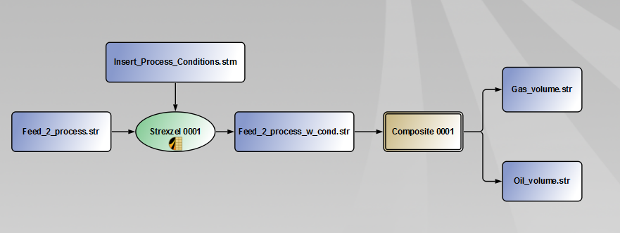
You can rename the composite "Process Simulation".
To navigate inside the composite, you only to double click on it.Navigation t upper level can be done using the arrows of the tool bar or by double clicking on the sockets.
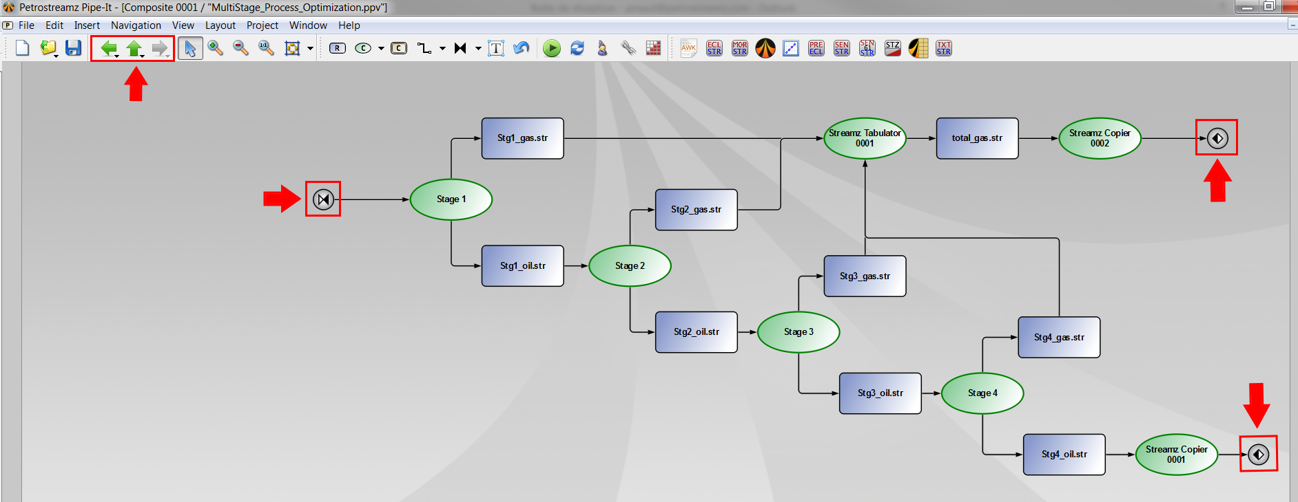
The Pipe-It project can be run.
You can look at the influence of changing some of the process conditions (in the file "Insert_Process_Conditions.stm") on the final oil and gas volumes.
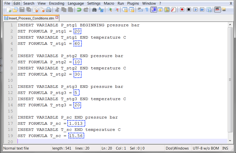
Each time a modification is done, the entire Pipe-It project needs to be launched.
We have seen in the previous section that the process conditions have an impact on the final oil volume. In this section, we are going to try to maximize the oil rate by changing the process conditions. We can eventually add some topside constraints: (1) Maximum pressure for the first stage separator; (2) minimum and maximum pressure for the other stages and (3) Minimum and maximum temperature. Note that the feed stream (mixture and molar rates) will remain unchanged.
The optimization problem we are going to consider is quite simple.
Maximize the final oil rate:
![\[
\textrm{maximize } q_o,
\]](tracmath/12c97fcf9d4afe52179e5d428b7a6391ca271aa8.png)
by changing the process conditions:
![\[
p_1,T_1,p_2,T_2,p_3 \textrm{ and } T_3,
\]](tracmath/b3d49f2fa067cfb0d3dc2d3e0f0b94064b7fc2ed.png)
and subject to:
![\[
p_1 < 50 \textrm{ bara},
\]](tracmath/9f3ebfa95a776fd327cdd2f366563dff277e17d2.png)
![\[
p_1 > p_2,
\]](tracmath/a01200362a1110f7de232ed02310f7fdd751fde4.png)
![\[
p_2 > p_3,
\]](tracmath/27d0287bcf7805f4d410cfaedaf0797c5cce7953.png)
![\[
p_3 > 1.013 \textrm{ bara},
\]](tracmath/4ffb87b4afcdde2ecdb5a27d27d97ffffd7c8d45.png)
![\[
50 \textrm{ C} <T_1 < 70 \textrm{ C},
\]](tracmath/2e62b8fc4530671e75f57df484905853ff06b722.png)
![\[
25 \textrm{ C} <T_2 < 45 \textrm{ C},
\]](tracmath/690142e138fe4af63d4b120cb55ed04465652bfb.png)
and
![\[
18 \textrm{ C} <T_3 < 22 \textrm{ C}.
\]](tracmath/1a663906c5e4376475a8ced555955e1f3a9e1b14.png)
The first step is to link the input files and output files. This can be done using Pipe-It built-in utility called Linkz. It allows to open any ASCII file and pin-point the number you want to link. Each time you define a new link in an ASCII file, this link is added to the Linkz library. Pipe-It optimizer has access to the Linkz library. We will come to that later on.
Select the resource element "Insert_Process_Conditions.stm" and right-click on it.
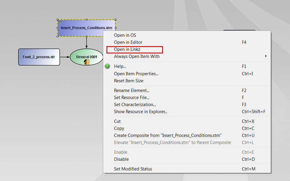
A new window appears:
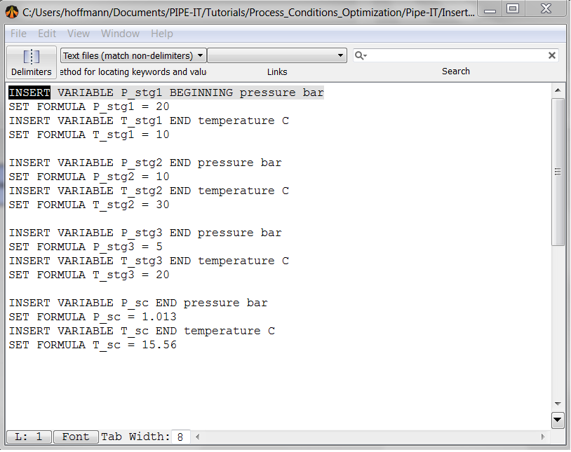
The last separator being the separation at standard conditions, the parameters we want to optimize are:
To create a link for P_Stg1, follow the next steps:
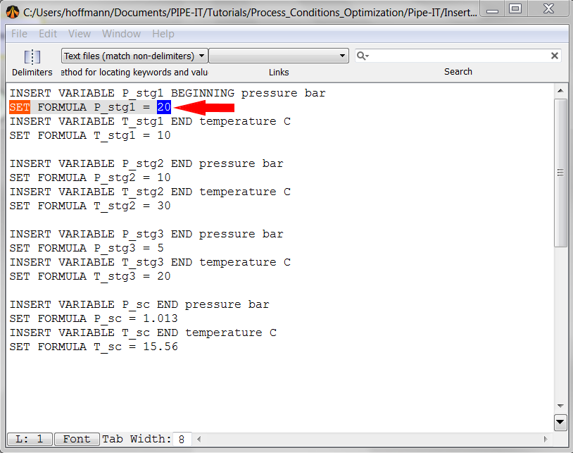
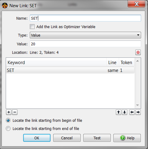
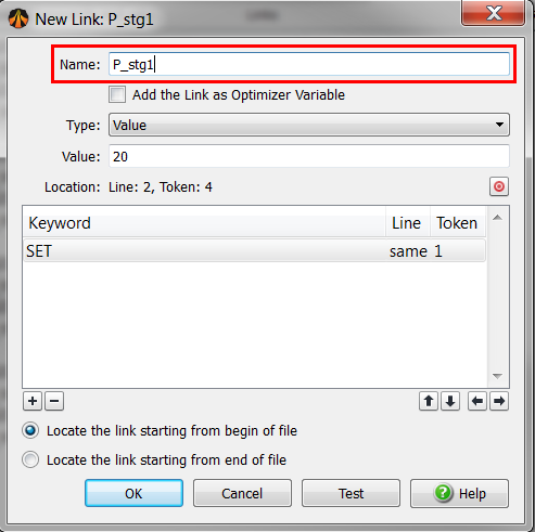
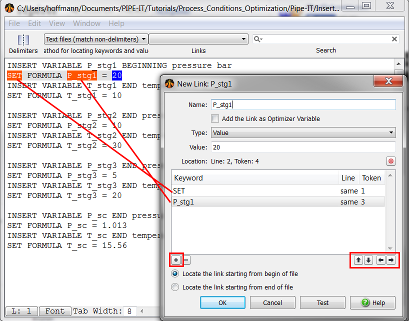
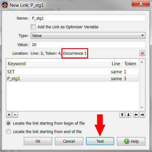
The link has been created and added to the Linkz library. You can check this by opening it:

A new window appears:
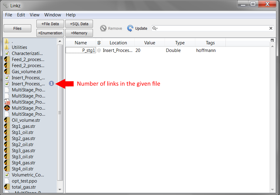
Use the same procedure to define links for the other process conditions. Keep the same nomenclature.
We now need to link the final oil volume. Open the resource file "Oil_volume.str" in Linkz. Create a link for the oil rate (pin-point the number "615.286") using the same procedure as described above. Rename the link "Oil_rate" and choose "DATA" as single keyword for this link.
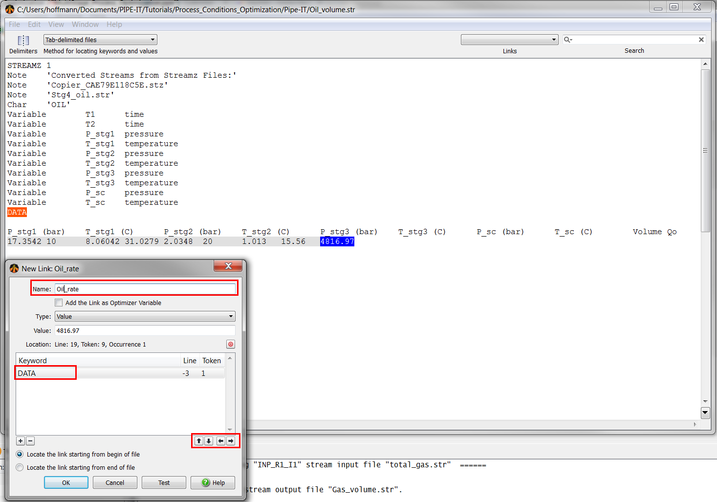
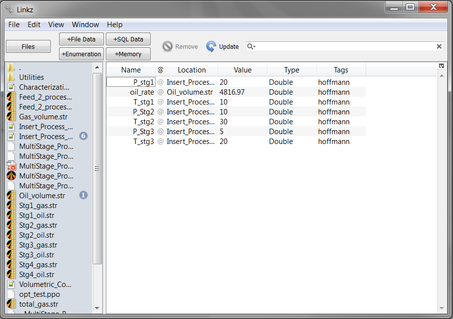
If you open the Linkz library, it should look like this:
Pipe-It Optimizer is a user-friendly optimization tool that allows to do model-based (or black box) optimization. Several built-in solvers are available: IPOPT, reflection, simplex... For each solver iteration, variables are changed in the input files (through user-defined links), the model is launched. Objective function and constraints are then read by the optimizer (using user-defined links). The solver decides the values of the variables for the next iteration.
To open Pipe-It optimizer, you can either:

A new window appears:
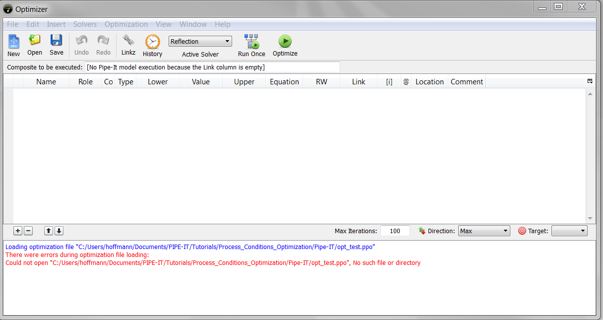
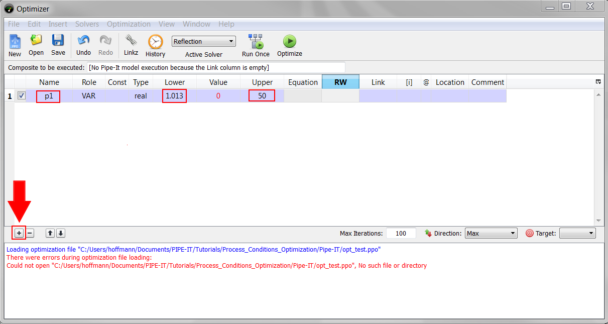
To add a new variable, click on the button + of the optimizer. Change the name of the variable in the column "Name" and rename it "p1". In addition, change the upper and lower limits to 1.013 for the lower bound and 50 for the higher bound.
Now, we need to link this optimizer variable to an actual number in one of the input file. We will use the linkz library for this. Double-click on the cell "Link" of the current row. A new window appears. Select "P_stg1" and click on "OK".
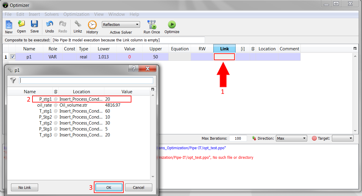
The optimizer variable "p1" is now mapped to the link "P_stg1". After each iteration, the value of this link in the file "Insert_Process_Conditions.stm" will be changed automatically.
Add the remaining variables following the following instructions:
| Name | Lower Bound | Upper Bound | Link |
|---|---|---|---|
| p2 | 1.013 | 50 | P_Stg2 |
| p3 | 1.013 | 50 | P_Stg3 |
| T1 | 50 | 70 | T_Stg1 |
| T2 | 25 | 45 | T_Stg2 |
| T3 | 18 | 22 | T_Stg3 |
At this moment, the optimizer window should look like this:
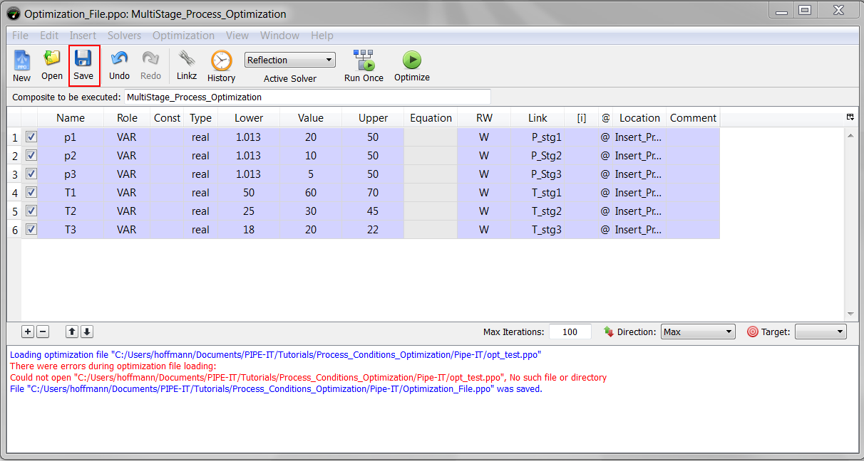
You can save the optimizer settings by clicking on the "Save" button in the optimization window.
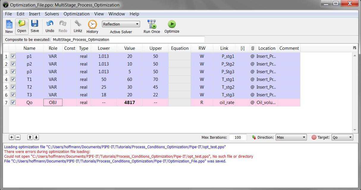
To add an objective, use the + button. Rename the variable "Qo" and change its "role" to "OBJ". Then link this variable to "Oil_volume".
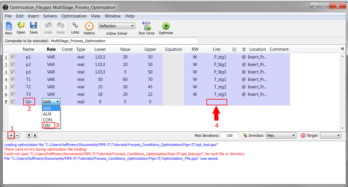
The optimizer window should now look like this:
It is not directly possible to include inequality constraints between two variables in the optimizer. However, we can note the equivalency:
![\[
p_1 > p_2 \Leftrightarrow p_1-p_2 > 0.
\]](tracmath/8d808ecbd850d60b93ab295016b66a24472bcca6.png)
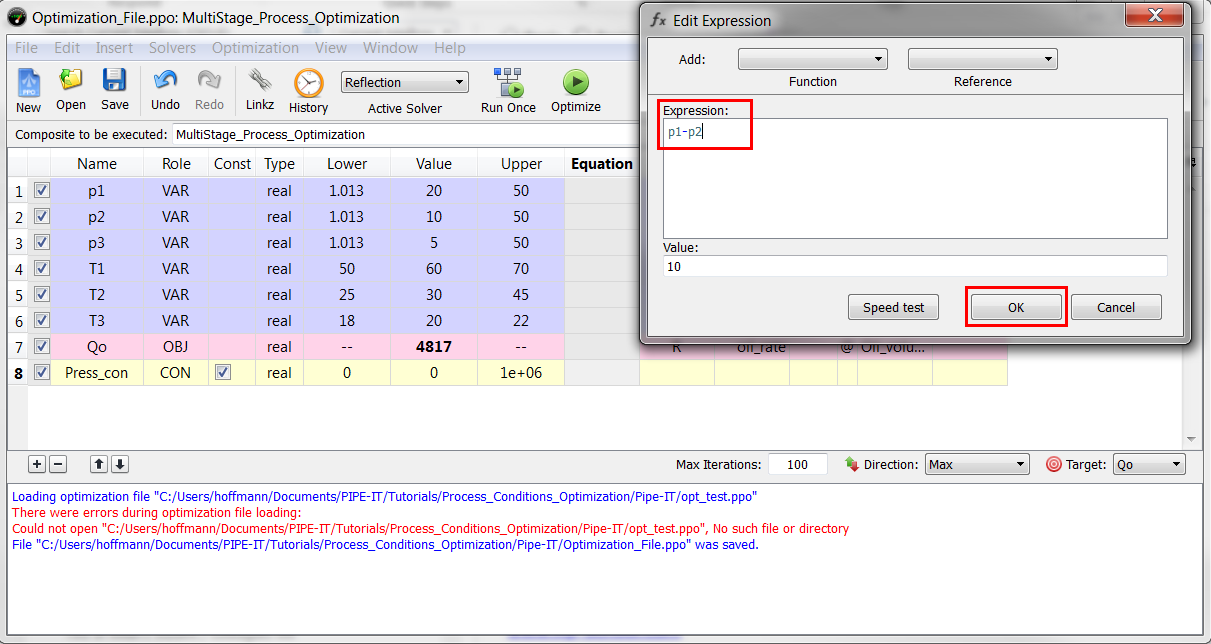
To add a this new constraint, use the + button. Rename the variable "Press_con". Set the lower bound to 0 and the upper bound to 1 000 000. Change its role to "CON". Then double-click on the corresponding "Equation" cell.
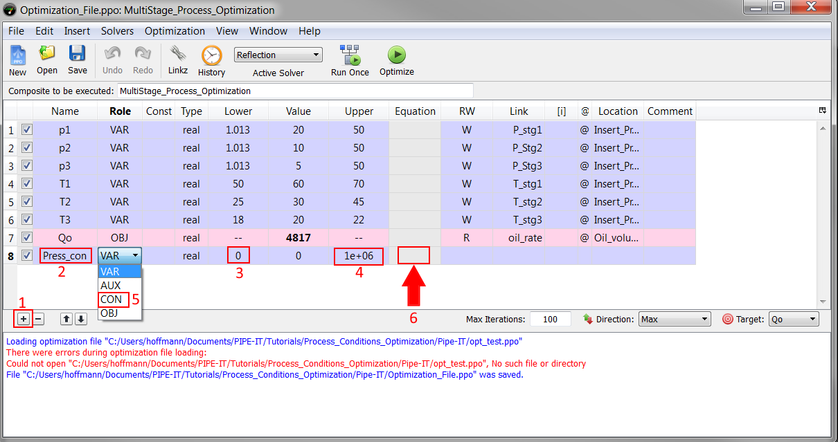
A new window appears. In the input box "Expression", type:
p1-p2
Then click "OK".
Add the remaining constraint following the same instruction. Name it "Press_con1". Note that the equation which needs to be entered is:
p2-p3
The optimizer window should look be similar to this:
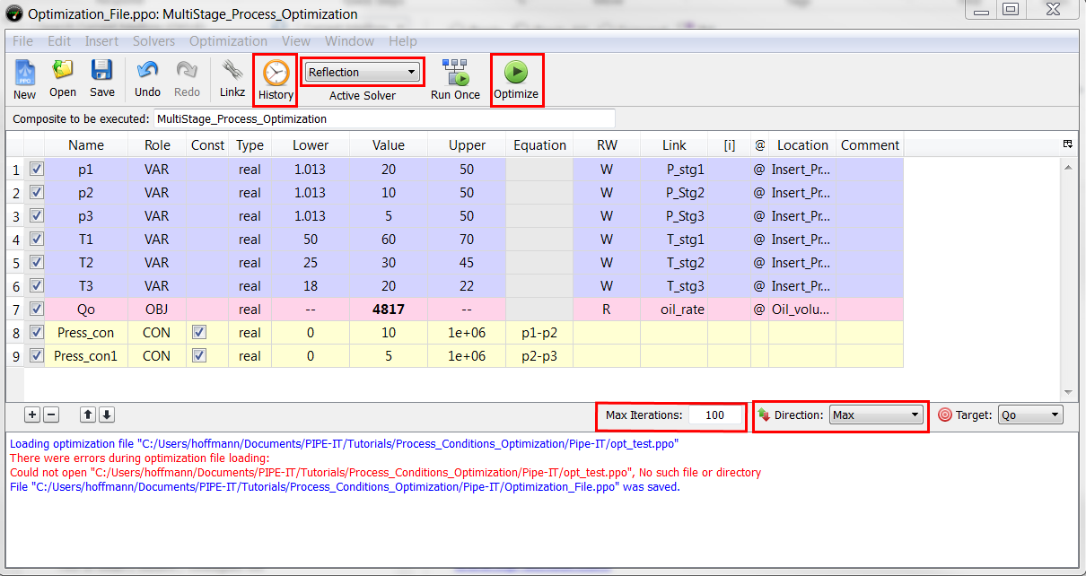
It is possible now to launch the optimization by clicking on "Optimize". Some additional settings are available:
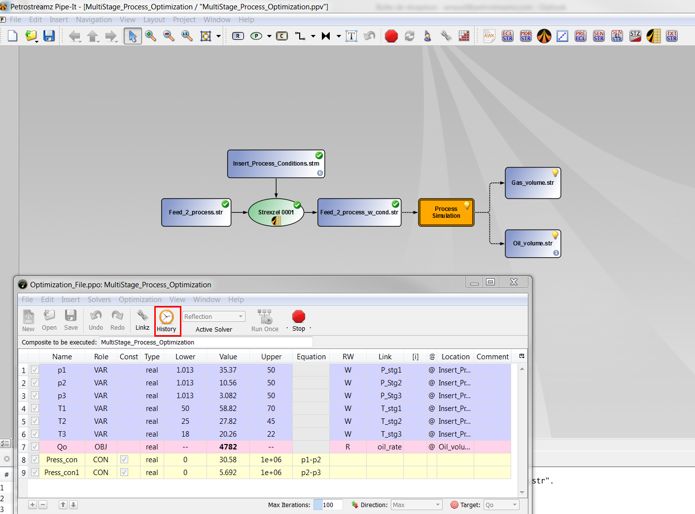
It is possible to access the history of the optimization by clicking on the "History" button.
Here are some ideas for further studies:
